ElectroCicla
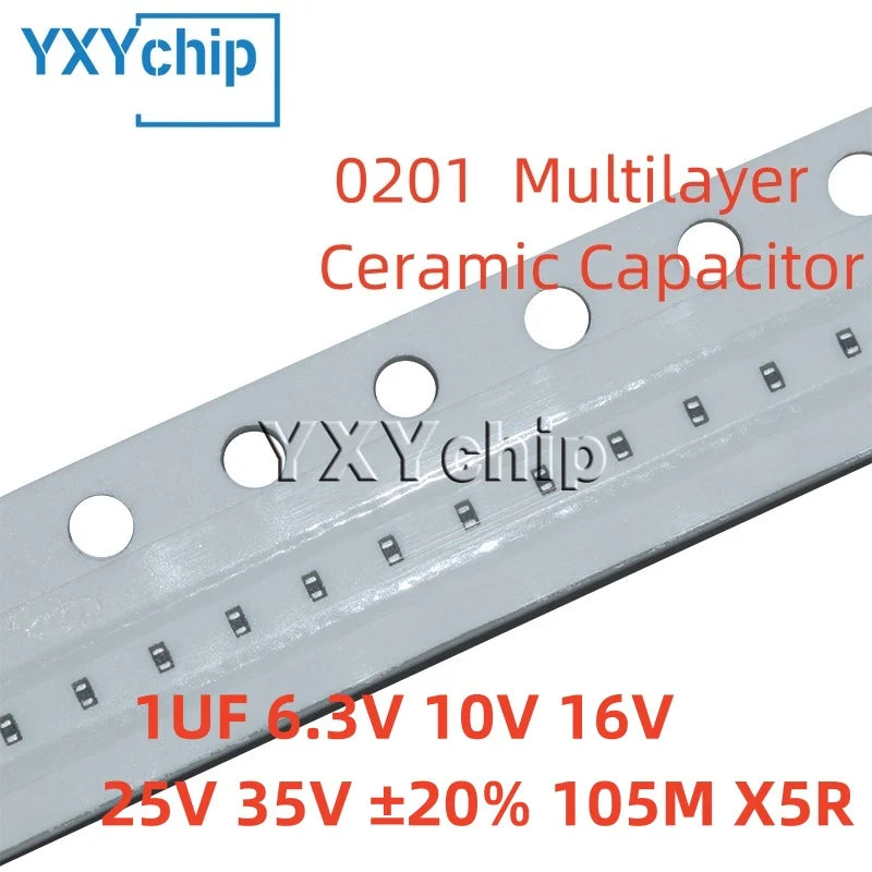
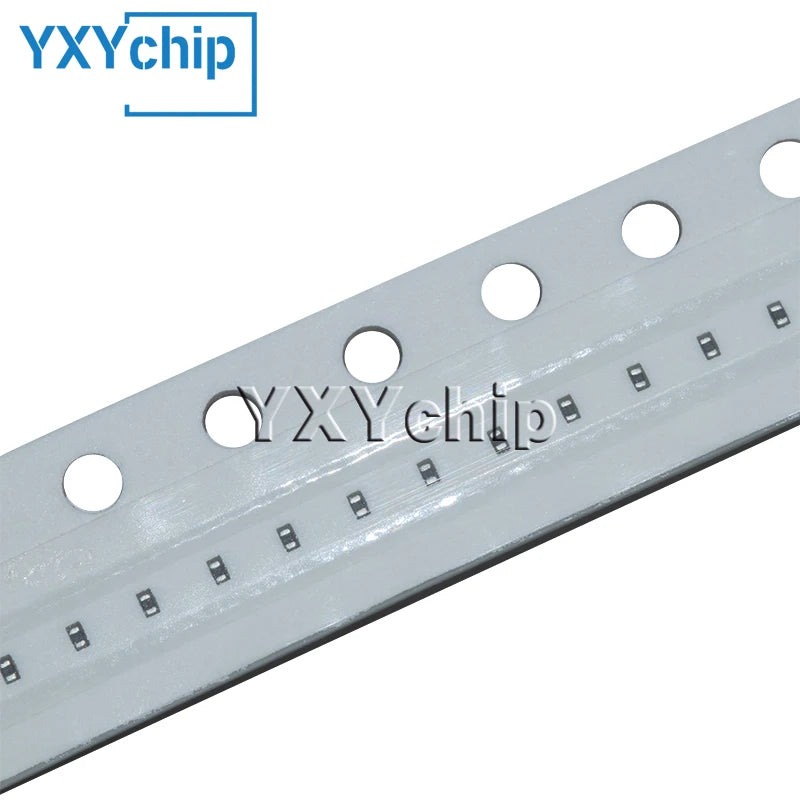
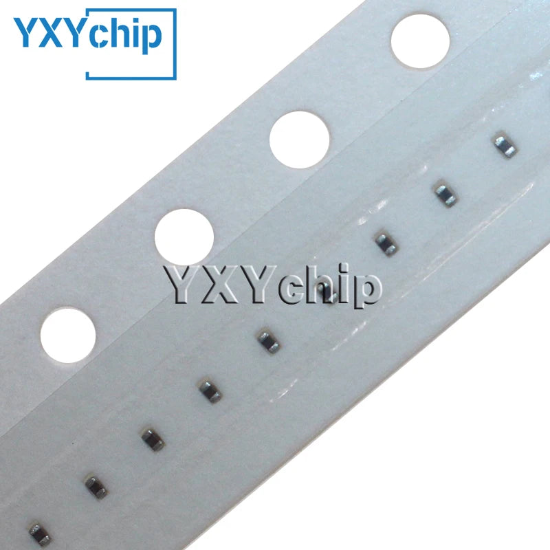
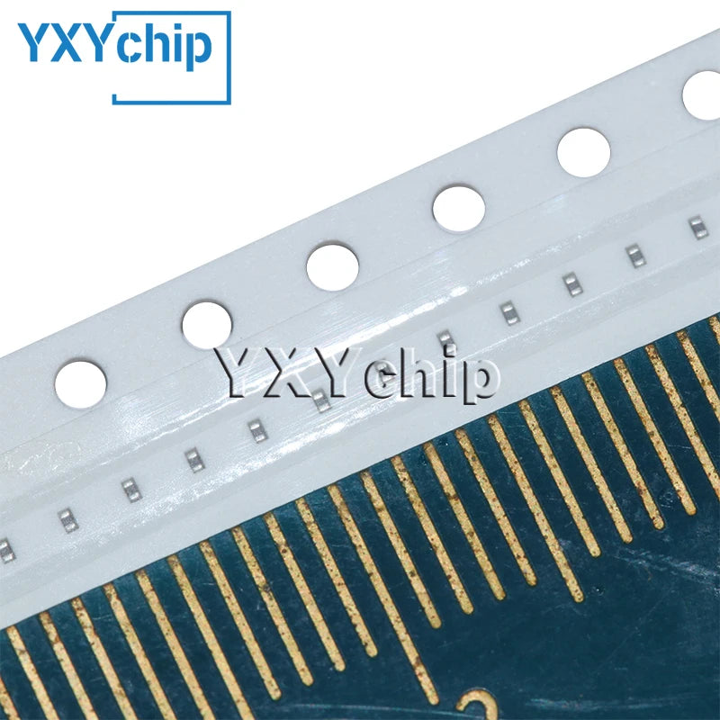
Capacitor Cerámico Multicapa Chip SMD 0201 (1uF 105M, 6.3V-35V, X5R 20%) - Pack 100 Unidades
Capacitor Cerámico Multicapa Chip SMD 0201 (1uF 105M, 6.3V-35V, X5R 20%) - Pack 100 Unidades
No se pudo cargar la disponibilidad de retiro
SPECIFICATIONS
Brand Name: YXYchip
Choice: yes
Model Number: 0201 1UF 6.3V 10V 16V 25V 35V ±20% 105M X5R
Origin: Mainland China
Type: Ceramic Capacitor
semi_Choice: yes
Chip capacitor full name: multi-layer (laminated, laminated) chip ceramic capacitor, also known as chip capacitor, chip capacity.
Full English name: Multiplayer Ceramic Chip Capacitors. English abbreviation: MLCC.
Multi-layer Ceramic Chip Capacitors are classified into NPO, X7R, Z5U
catalogue
1 size 3 package 5 MLCC capacitor selection
2 Naming 4 Classification 6 Action 7 Internal structure
1 Size editing
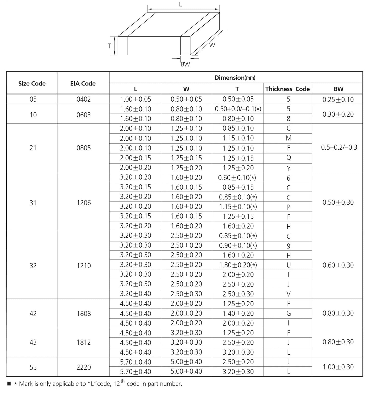
There are two dimensional representations of the chip capacitance, one of which is expressed in inches
One is expressed in millimeters, the series models of the chip capacitor are 0402, 0603, 0805, 1206, 1210, 1808, 1812, 2010, 2225, 2512,
these are inch notation, 04 means the length is 0.04 inches, 02 means the width is 0.02 inches, Other similar size (mm)
British dimensions Metric dimensions Length and tolerance Width and tolerance thickness and tolerance
0402 1005 1.00±0.05 0.50±0.05 0.50±0.05
0603 1608 1.60±0.10 0.80±0.10 0.80±0.10
0805 2012 2.00±0.20 1.25±0.20 0.70±0.20 1.00±0.20 1.25±0.20
1206 3216 3.00±0.30 1.60±0.20 0.70±0.20 1.00±0.20 1.25±0.20
1210 3225 3.00±0.30 2.54±0.30 1.25±0.30 1.50±0.30
1808 4520 4.50±0.40 2.00±0.20 ≤2.00
1812 4532 4.50±0.40 3.20±0.30 ≤2.50
2220 57505.70±0.40 5.00±0.30 ≤2.50
2225 5763 5.70±0.50 6.30±0.50 ≤2.50
3035 7690 7.60±0.50 9.00±0.05 ≤3.00
2 Naming and Editing
The parameters included in the naming of the chip capacitor are the size of the chip capacitor, the material used to make the chip capacitor,
the accuracy required, the required voltage, the required capacity, the requirements of the end and the requirements of the packaging. Generally,
the parameters required to order the chip capacitor should be the size, the required accuracy, the voltage requirements, the capacity value,
and the required brand.
Name of chip capacitor:
0805CG102J500NT 0805: refers to the size of the chip capacitor, which is expressed in inches.08 means the length is 0.08 inches, 05 means the width is 0.05 inches CG:
This material is generally suitable for making capacitors less than 10000PF, 102: refers to the capacity of the capacitor, the first two digits are significant numbers,
the following 2 indicates how many zeros 102=10×100, that is, = 1000PF J: It is required that the error accuracy of the capacity value of the capacitor is 5%,
and the dielectric material and the error accuracy are paired 500: it is required that the voltage withstand of the capacitor is 50V, and the first two digits of 500 are
significant numbers, followed by how many zeros there are. N: refers to the end material, now the general end refers to three layers of electrodes (silver/copper layer),
nickel, tin T: It refers to the packaging method, T stands for ribbon packaging, and the color of the chip capacitor, which is usually a little lighter than the cardboard box
yellow and bluish gray, which will have different differences in the specific production process, there is no printing on the chip capacitor, which is related to his production
process (the chip capacitor is made of high temperature sintering surface, so there is no way to print on its surface). The patch resistance is made of screen printing (can print marks).
Chip capacitors have medium and high voltage chip capacitors and ordinary chip capacitors. The series voltage has 6.3V, 10V, 16V, 25V, 50V, 100V, 200V, 500V, 1000V, 2000V, 3000V,
4000V chip capacitors. There are two dimensional representations, one is expressed in inches. One is expressed in millimeters, and the models of the chip capacitor series are 0201,
0402, 0603, 0805, 1206, 1210, 1812, 2010, 2225 and so on. The material of the chip capacitor is generally divided into three kinds, NPO,X7R,Y5V NPO This material has the most
stable electrical performance, almost does not change with the change of temperature, voltage and time, and is suitable for high frequency circuits with low loss and stability requirements.
The capacity accuracy is about 5%, but this material can only be used for smaller capacity, conventional 100PF below, 100PF-1000PF can also be produced but the price is higher.
X7R This material is less stable than NPO, but the capacity is higher than NPO's material, and the capacity accuracy is about 10%. The capacitance of such media as Y5V is poor in stability,
the capacity deviation is about 20%, and it is more sensitive to temperature and voltage, but this material can achieve a high capacity, and the price is low, and it is suitable for circuits with
little temperature change.
3 Package Editing
Chip capacitors: can be divided into non-polar and polar two categories, non-polar
Capacitors The following two types of packages are the most common, namely 0805, 0603; The polar capacitor is what we usually call the electrolytic capacitor, generally we usually
use the most for the aluminum electrolytic capacitor, because its electrolyte is aluminum, so its temperature stability and accuracy are not very high, and the chip element because
of its close to the circuit version, so the temperature stability is required to be high, so the chip capacitor is more than the tantalum capacitor, according to its different voltage
resistance, The chip capacitor can be divided into A, B, C, D four series,
The specific categories are as follows: Type Package type Withstand voltage
A 3216 10V
B 3528 16V
C 6032 25V
D 7343 35V
4 Category Editing
Classification of chip capacitors
An NPO capacitor
Two X7R capacitors
Three Z5U capacitors
Four Y5V capacitors
Differences: The main difference between NPO, X7R, Z5U and Y5V is their different filling media. Under the same volume, the capacity of the capacitor composed of different
filling media is different, and the resulting dielectric loss and capacity stability of the capacitor are also different. Therefore, when using capacitors, different capacitors should
be selected according to the different roles of capacitors in the circuit.
5 NPO capacitors
NPO is one of the most commonly used monolithic ceramic capacitors with temperature compensation characteristics. Its filling medium is composed of rubidium, samarium
and some other rare oxides.
NPO capacitors are one of the most stable capacitors in terms of capacitance and dielectric loss. At temperatures from -55 ° C to 125 ° C, the capacitance changes to 0±30ppm/ ° C,
and the capacitance changes with frequency to less than ±0.3ΔC. The drift or lag of NPO capacitors is less than ±0.05%, which is negligible compared to thin film capacitors greater
than ±2%. The typical variation in capacity relative to service life is less than ±0.1%. The capacitance and dielectric loss of NPO capacitors vary with frequency depending on the
package form, and the frequency characteristics of large package size are better than that of small package size. The following table shows the optional capacity range of NPO capacitors.
Sealed DC=50V DC=100V
0805 0.5---1000pF 0.5---820pF
1206 0.5---1200pF 0.5---1800pF
1210 560---5600pF 560---2700pF
2225 1000pF---0.033μF 1000pF---0.018μF
NPO capacitors are suitable for slot capacitors in oscillators, resonators, and coupling capacitors in high-frequency circuits.
X7R capacitor
The X7R capacitor is known as a temperature-stable ceramic capacitor. When the temperature is -55 ° C to 125 ° C, the capacity change is 15%, it should be noted that the
capacitor capacity change is non-linear at this time.
The capacity of the X7R capacitor is different under different voltage and frequency conditions, and it also changes with time, changing about 1%ΔC every 10 years,
showing a change of about 5% over 10 years.
X7R capacitors are mainly used in less demanding industrial applications where the capacity change is acceptable when the voltage changes. Its main feature is that the
power capacity can be relatively large under the same volume. The following table shows the capacity ranges available for X7R capacitors.
Sealed DC=50V DC=100V
0805 330pF---0.056μF 330pF---0.012μF
1206 1000pF---0.15μF 1000pF---0.047μF
1210 1000pF---0.22μF 1000pF---0.1μF
2225 0.01μF---1μF 0.01μF---0.56μF
Z5U capacitor
Z5U capacitors are called "universal" ceramic monolithic capacitors. The first thing to consider here is the use of temperature range, the main thing for Z5U capacitors is
its small size and low cost. For the above three ceramic monolithic capacitors, it is said that the Z5U capacitor has the largest capacitance under the same volume. However,
its electrical capacity is greatly affected by the environment and working conditions, and its aging rate can decrease by up to 5% every 10 years.
Despite its unstable capacity, due to its small size, low equivalent series inductance (ESL) and equivalent series resistance (ESR), and good frequency response, it has a wide
range of applications. Especially in the application of decoupling circuits. The following table gives the range of values for Z5U capacitors.
Sealed DC=25V DC=50V
0805 0.01μF---0.12μF 0.01μF---0.1μF
1206 0.01μF---0.33μF 0.01μF---0.27μF
1210 0.01μF---0.68μF 0.01μF---0.47μF
2225 0.01μF---1μF 0.01μF---1μF
Other technical indicators of Z5U capacitors are as follows:
Operating temperature range 10℃ -85 ℃
Temperature characteristic 22% ---- -56%
The maximum dielectric loss is 4%
Y5V capacitor
The Y5V capacitor is a general purpose capacitor with a certain temperature limit, and its capacity can vary from 22% to -82% in the range of -30 ° C to 85 ° C.
Y5V's high dielectric constant allows capacitors up to 4.7μF to be manufactured at small physical sizes.
The following table shows the value range of Y5V capacitors
Sealed DC=25V DC=50V
0805 0.01μF---0.39μF 0.01μF---0.1μF
1206 0.01μF---1μF 0.01μF---0.33μF
1210 0.1μF---1.5μF 0.01μF---0.47μF
2225 0.68μF---2.2μF 0.68μF---1.5μF
Other technical indicators of Y5V capacitors are as follows:
Operating temperature range -30℃ -85 ℃
Temperature characteristics 22% ---- -82%
The maximum dielectric loss is 5%
Naming methods for chip capacitors can be found on the AVX website. Different companies may have slightly different naming methods.
MLCC capacitor selection editing
Main MLCC Main manufacturer: ********.
There are many factors that need to be considered when capacitance shape selection. The following discusses the capacitor shape selection elements of MLCC.
Selection element
- Parameters: capacitance value, tolerance, voltage resistance, operating temperature, size
- Material
- DC bias effect
- Disabled
- Price and availability
The properties of different media determine the different applications of MLCC
-C0G capacitors have high temperature compensation characteristics, suitable for use as bypass capacitors and coupling capacitors
-X7R capacitors are temperature-stable ceramic capacitors suitable for less demanding industrial applications
Z5U capacitors are characterized by their small size and low cost and are particularly suitable for use in decoupling circuits
Y5V capacitors have the worst temperature characteristics, but large capacity and can replace low-volume aluminum electrolytic capacitors
MLCC commonly used C0G(NP0), X7R, Z5U, Y5V and other different media specifications, different specifications have different characteristics and uses. The main difference between
C0G, X7R, Z5U and Y5V is their different filling media. In the same volume due to the filling medium of different capacitor capacity is different, the resulting capacitor dielectric loss,
capacity stability, etc., is different, so in the use of capacitors should be based on the capacitor in the circuit to choose different capacitors.
Function editing
Function in a circuit
In a direct current circuit, a capacitor is equivalent to an open circuit. A capacitor is a device that stores electrical charge and is one of the most commonly used electronic components.
It starts with the structure of the capacitor. The simplest capacitor consists of a plate at both ends and an insulating dielectric (including air) in the middle. After power, the plate is charged,
forming a voltage (potential difference), but because of the insulating material in the middle, the entire capacitor is not conductive. However, this is the case without exceeding the critical
voltage of the capacitor (breakdown voltage) under the premise. We know that any substance is relatively insulated, when the voltage at both ends of the substance increases to a certain
extent, the substance can conduct electricity, we call this voltage is called breakdown voltage. The capacitor is no exception, after the capacitor is broken down, it is not an insulator.
However, in the middle school stage, such a voltage is not seen in the circuit, so it is working below the breakdown voltage and can be seen as an insulator. Ceramic capacitor
However, in AC circuits, because the direction of the current is a certain function of time changes. The process of capacitor charge and discharge is time, this time, the formation of a
changing electric field between the plates, and this electric field is also a function of time change. In fact, the current is passed between capacitors in the form of a field.
In the middle school stage, there is a saying, called AC, DC resistance, that is, this property of capacitance.
5 The role of capacitors:
1) Bypass
The bypass capacitor is an energy storage device that provides energy to the local device, which can homogenize the output of the regulator and reduce the load demand. Just
like a small rechargeable battery, the bypass capacitor can be charged and discharged to the device. To minimize impedance, the bypass capacitor should be as close to the power
supply pin and ground pin of the load device as possible. This can well prevent the ground potential elevation and noise caused by too large input value. The ground potential is the
voltage drop when the ground connection passes through a large current burr.
2) Decoupling
Decoupling, also known as decoupling. In terms of the circuit, it is always possible to distinguish between the driving source and the driven load. If the load capacitance is relatively large,
the drive circuit to charge the capacitor, discharge, in order to complete the signal jump, when the rising edge is relatively steep, the current is relatively large, so that the drive current
will absorb a large power current, due to the inductance in the circuit, resistance (especially the inductance on the chip pin, will produce rebound), This current is actually a noise relative
to normal conditions, which will affect the normal operation of the preceding stage, which is the so-called "coupling".
The decoupling capacitor acts as a "battery" to meet the changes in the drive circuit current and avoid coupling interference between each other.
Combining bypass capacitors and decoupling capacitors will be easier to understand. The bypass capacitor is actually decoupled, but the bypass capacitor generally refers to the
high-frequency bypass, that is, to improve the high-frequency switching noise of a low impedance leakage path. The high-frequency bypass capacitance is generally small, and the
resonant frequency is generally 0.1μF, 0.01μF, etc. The capacity of the decoupling capacitor is generally large, perhaps 10μF or more, depending on the distributed parameters in the
circuit and the change in the drive current. Bypass is to filter the interference in the input signal as the object, and decoupling is to filter the interference in the output signal as the
object to prevent the interference signal from returning to the power supply. This should be their essential difference.
3) Filtering
In theory (that is, if the capacitor is a pure capacitor), the larger the capacitor, the smaller the impedance, and the higher the frequency of passing. But in fact, more than 1μF
capacitors are mostly electrolytic capacitors, have a large inductance component, so the impedance will increase after high frequency. Sometimes it will be seen that there is
a large capacitance electrolytic capacitor in parallel with a small capacitor, at which time the large capacitor passes the low frequency and the small capacitor passes the high
frequency. The role of the capacitor is to pass high and low resistance, and pass high frequency and low frequency. The larger the capacitance, the easier it is for low frequencies
to pass through. Specifically used in filtering, large capacitance (1000μF) filter low frequency, small capacitance (20pF) filter high frequency. Some netizens have likened the filter
capacitor to a "pond". Since the voltage at both ends of the capacitor does not change, it can be seen that the higher the signal frequency, the greater the attenuation, it can
be said that the capacitor is like a pond, and the water amount will not change due to the addition or evaporation of a few drops of water. It converts changes in voltage into
changes in current, and the higher the frequency, the greater the peak current, thereby buffering the voltage. Filtering is the process of charging and discharging.
4) Energy storage
The energy storage capacitor collects the charge through the rectifier and transmits the stored energy to the output of the power supply through the converter lead.
Aluminum electrolytic capacitors with voltage ratings of 40 ~ 450VDC and capacitance values between 220 ~ 150000 μF (such as EPCOS B43504 or B43505) are more
commonly used. Depending on the power requirements, the device will sometimes be in series, parallel or a combination of the form, for power levels of more than 10KW
power supplies, usually use a larger volume of can-shaped spiral terminal capacitors.
7 Edit internal structure
Its appearance is made of ceramic, but there is more than one, it is also divided into glass capacitors, oil paper capacitors, electrolytic capacitors and so on.
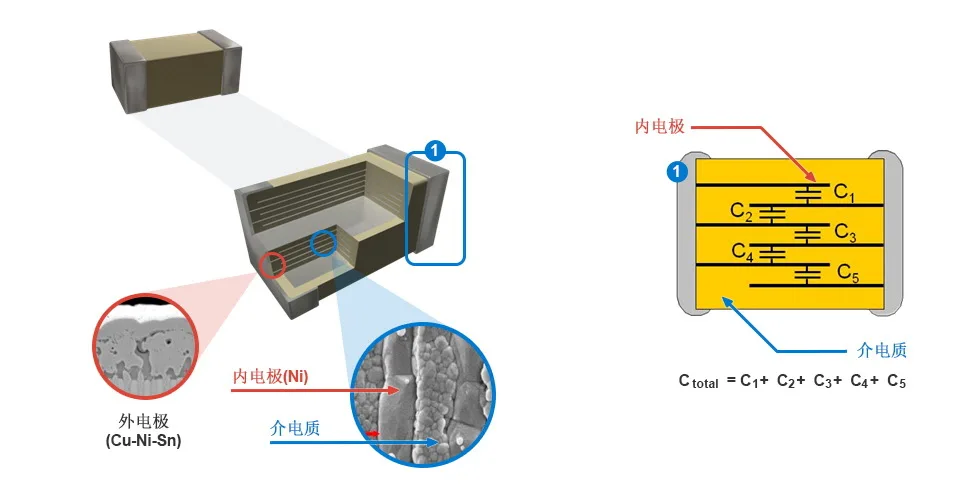
Usually referred to as Ceramic chip Capacitors refers to MLCC, that is, Multilayer Ceramic Capacitors.
According to the material divided into conventional patch capacitance COG (NPO), X7R and Y5V, encapsulating the pin 0201040 2060 3.0805. 1206121, 0181, 2182, 5222.
Multilayer ceramic capacitors (MLCC) are composed of parallel ceramic materials and electrode materials stacked in layers.
8 Applications
General electronic equipment
Mobile device
Server PC Tablet
Power supply circuit
9 Features
The monolithic structure guarantees excellent mechanical strength and high reliability
Due to the good low frequency characteristics of ESR ESL, it is more advantageous to design a loop close to the theoretical value.
Low spontaneous heat due to low ESR can withstand higher ripple current.
Infinitus.


Compartir
